EnglishEnglish
Have you ever wondered how curved pipes in car exhaust systems, building plumbing, or industrial machinery are created? The answer lies in pipe bending—a critical manufacturing process that transforms straight metal pipes into precise curves and angles. This comprehensive guide explores everything you need to know about the pipe bending process, from fundamental techniques to advanced CNC technology and best practices.
Pipe bending is the specialized process of reshaping straight pipes or tubes to achieve specific angles and curves without compromising structural integrity. By applying carefully controlled force—and sometimes heat—metal pipes are transformed into exact shapes needed for various applications. This technique is fundamental to creating custom piping systems that navigate obstacles, fit within tight spaces, and create efficient connections.
The pipe bending process involves more than simply forcing a pipe into a new shape. It requires precise calculations, proper equipment selection, and skilled execution to maintain the pipe's cross-sectional area, wall thickness, and overall strength.

The importance of pipe bending extends across virtually every major industry. In construction, bent pipes create efficient HVAC systems and plumbing networks. The automotive industry relies on precision pipe bending for exhaust systems and chassis components. In oil and gas, bent pipes form pipeline infrastructure.
Key advantages of pipe bending:
Cost Efficiency: Eliminates multiple joints and fittings, reducing material and labor costs
Structural Integrity: Maintains continuous material without weak points from welding
Leak Prevention: Fewer joints mean fewer potential failure points
Space Optimization: Custom bends navigate obstacles more efficiently
Improved Flow: Smooth bends create less turbulence than sharp-angled fittings
Choose Pipe Bending When:
Working with low to medium pressure systems
Space constraints require custom routing
Minimizing leak points is a priority
Smooth flow characteristics are important
Choose Welded Elbows When:
Working with extremely high-pressure systems (>1,500 PSI)
Standard angles meet requirements
Low production volumes don't justify bending setup
Quick field modifications are needed
Neutral Axis: The theoretical centerline within a pipe's cross-section that experiences minimal compression or elongation during bending. Preserving this axis helps maintain structural integrity.
Bend Radius: Measures the distance from the centerline of the bend to the centerline of the pipe. Smaller radii create tighter bends but increase failure risk. Typically expressed as multiples of pipe diameter (2D, 3D, 5D).
Bend Angle: The degree of deviation from the original straight position. Common angles include 45°, 90°, and 180°.
Wall Thickness: Distance between inner and outer surfaces. Thicker walls provide more resistance to collapse but require greater bending force.
Ovality: Cross-sectional distortion during bending that flattens the circular shape. Excessive ovality (>8-10%) weakens pipes and causes sealing problems.
Springback: Natural tendency of bent pipes to partially return to their original shape after force is removed. Operators compensate by over-bending slightly.
Tangent Length: Straight sections before and after bends. Most operations require 2-6 times the pipe diameter for proper gripping.
Elongation on Outer Radius: Material stretches to accommodate the new shape, creating tensile stress that can cause thinning or cracking.
Compression on Inner Radius: Material is forced into smaller space, causing compressive stress that can lead to wrinkling or buckling.
Balancing Forces: Success requires carefully balancing these opposing forces through proper bend radius selection, mandrel use, external support dies, and precise control of speed and force.
Bend Allowance (BA): Additional length needed to create a bend, calculated as:
BA = (π × Angle × (Radius + K × Thickness)) / 180
Where K is typically 0.33 for most metals.
Bend Deduction (BD): Compensates for the difference between outside dimensions and actual material length:
BD = 2 × (R + T) × tan(θ/2) - BA
Accurate calculations prevent costly errors and ensure proper fit in assemblies.
The pipe bending industry employs five distinct methods, each with specific advantages and ideal applications:
Material type and properties
Pipe dimensions (diameter, wall thickness)
Required bend radius
Precision requirements
Production volume
Budget constraints
Mandrel bending employs internal support to maintain pipe integrity during forming. A mandrel (metal rod or linked ball assembly) is inserted inside the pipe before bending, providing crucial internal support that prevents walls from collapsing or wrinkling. After bending, the mandrel is carefully withdrawn, leaving a smooth, uniform interior surface.
Ideal applications:
Automotive exhaust systems: Smooth interiors optimize flow and performance

Structural components: Maintains uniform wall thickness for strength calculations
Furniture and handrails: Produces consistent, visually appealing results

Tight radius applications: Essential for radii less than 3× pipe diameter
Thin-wall tubing: Prevents collapse in walls less than 10% of diameter
Higher equipment costs and mandrel inventory investment
Setup complexity requiring skill and experience
Maintenance requirements for mandrel inspection and replacement
Additional production time for insertion and removal
Size limitations for very small or large diameter pipes
Rotary draw bending uses a rotating die to pull the pipe around a fixed form, creating accurate, repeatable bends. The process involves coordinated components:
Bending Die: Rotates to draw pipe around its circumference
Clamping Die: Securely grips pipe preventing slippage
Pressure Die: Maintains circular cross-section during bending
Wiper Die: Prevents wrinkle formation at tangent point
Mandrel (optional): Provides additional internal support
Architectural handrails requiring exact angles
Automotive roll cages for safety equipment
Industrial piping systems with numerous bends
HVAC ductwork for optimal airflow
Furniture manufacturing with uniform components
Complex shapes with multiple bends at different angles
Advantages:
Exceptional precision and repeatability (±0.5° typical)
Excellent surface quality
Suitable for wide range of materials
Efficient for medium to high production volumes
Limitations:
Dies must be tooled for each size and radius
Substantial initial tooling investment
Less economical for low volume work
May require mandrel for tight radii
Compression bending is the simplest method, pressing pipe against a stationary die using external force. Without internal support, the pipe is forced into shape through external pressure alone, making it quick to set up but limiting precision.
Basic construction projects and temporary structures
Low-pressure piping (agricultural irrigation, drainage)
Structural frameworks and scaffolding
Large-radius curves (5× diameter or greater)
Budget-constrained projects requiring minimal tooling
Deformation risk without internal support
Limited precision (±2° or worse)
Surface quality issues and marking
Wrinkling and buckling on inner radius
Excessive wall thickness variation
Roll bending uses three or four rollers to gradually form pipes into large-radius curves. The pipe passes through rollers repeatedly, with each pass applying incremental bending force. This progressive approach distributes stress gradually, allowing smooth plastic deformation without cracking.
Architectural arches and building features
Curved structural beams and roof trusses
Coils for heating, cooling, and heat exchangers
Large-diameter infrastructure pipes
Aesthetic features and artistic installations
Cylindrical storage tank construction
Cannot achieve tight radii (less than 5-10× diameter)
End waste requiring excess material
Operator skill dependent for consistency
Potential inconsistency in radius along pipe length
Limited precision compared to rotary draw methods
Significant springback requiring compensation
Heat induction bending uses localized heating to make material pliable for controlled forming. An induction coil heats a narrow band (1-2 inches) to 850-1050°C for steel, then mechanical force bends the softened material around a fixed radius arm. Controlled cooling immediately follows, ensuring proper material properties.
Ideal for:
Large-diameter pipelines (24+ inches, up to 100 inches)
High-strength materials resisting cold forming
Petrochemical industry piping for refineries
Power generation steam and water transport
Infrastructure projects and municipal systems
Shipbuilding for large vessels
Carbon steel (most common)
Stainless steel (austenitic and duplex grades)
Alloy steels (chrome-moly for high-temperature service)
Aluminum (requires careful temperature control)
Exotic alloys (Inconel, Monel, titanium)
Temperature Control: Precise management prevents property changes
Cooling Management: Critical for final material properties
Operator Expertise: Requires skilled, experienced operators
Time Requirements: 30-60+ minutes for large bends
Quality Assurance: Post-bend inspection and material testing essential
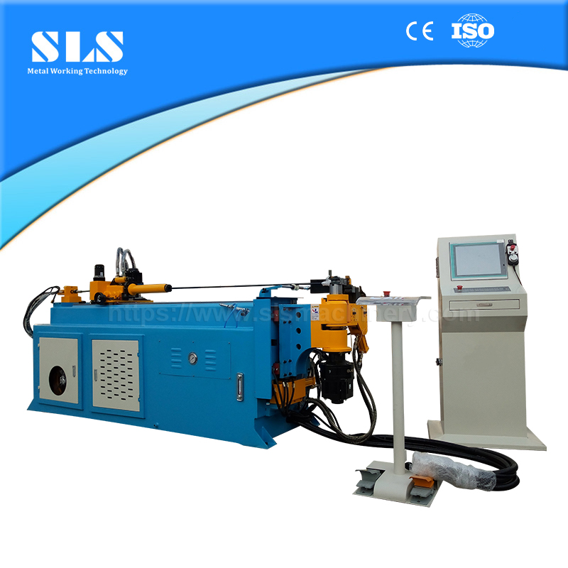
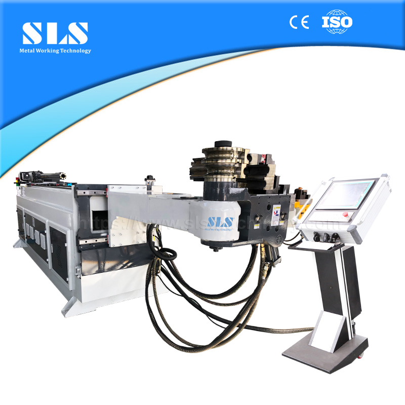
CNC (Computer Numerical Control) pipe bending machines combine precision mechanics with advanced computer control to automate the entire pipe bending process. These systems eliminate human error, dramatically increase production speed, and enable complex three-dimensional components impossible to produce manually.
Key advantages:
Precision: Accuracy within ±0.1° and ±0.5mm
Repeatability: Identical parts indefinitely
Complexity: Multiple bends in different planes automatically
Efficiency: Automated operation increases throughput
Quality Assurance: Real-time error detection
Core mechanical components:
Bed Frame: Rigid foundation providing precise mounting references
Bending Die: Defines bend radius and secures pipe
Pressure Die: Prevents wrinkling and maintains cross-section
Mandrel System: Internal support for tight radius bends
Bending Arm: Primary actuator rotating to form bend
Servo-Driven Feeding (X-Axis): Precise longitudinal positioning
Tube Rotation (Y-Axis): Enables multi-plane bends
Control systems:
High-precision CNC controller coordinating all movements
Hydraulic or electric servo power systems
Safety measurement devices and interlocks
Touchscreen user interface
High-quality bed frames feature high-strength steel plates welded into rigid box-type structures with dense rib reinforcement. Precision machining and stress-relief treatment create a stable foundation that minimizes vibration, maintains alignment, and ensures long-term accuracy.
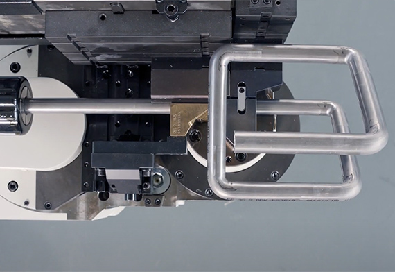
The bending head assembly contains components that physically form the pipe under unified CNC control:
Bending die and arm: Work together for rotational deformation
Clamping die: Secures tube preventing slippage
Pressure die: Suppresses wrinkles maintaining shape
Mandrel: Provides internal support preventing collapse
Wiper die: Smooths inner radius preventing wrinkles
Guide units: Maintain alignment throughout process
1. Real-Time 3D Processing Simulation:
Visual preview before physical bending
Interference and error prediction
Elimination of trial-and-error costs
Virtual problem resolution
2. Multi-Program Storage Function:
Single-click program saving and retrieval
Easy work order management
Rapid production task switching
Digital program backup and sharing
3. Intuitive User Interface:
Touchscreen operation with graphical programming
Quick parameter setting without specialized knowledge
Drastically reduced learning curve
Error prevention through intelligent checking
CNC Tube Bending Machines: General-purpose versatile systems
Automatic Pipe Bending Machines: Fully automated with material handling
Mandrel Pipe Bending Machines: High internal quality for exhaust systems
Steel Pipe Bending Machines: Heavy-duty for high-strength applications
Profile Pipe Bending Machines: Square and rectangle pipe capability
Hydraulic Pipe Bending Machines: Heavy-duty forming operations
Electric Servo-Drive Systems: Efficient, clean, precise operation
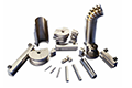
External shaping dies:
Bending Die: Defines radius with hardened, polished groove
Clamping Die: Secures with matched profile
Pressure Die: Maintains cross-section with adjustable force
Wiper Die: Prevents wrinkles with precise geometry
Internal support mandrels:
Ball-Style: Articulated segments for complex bends
Flexible Hose-Style: Polymer core for standard curves
Custom-Designed: Application-specific for specialized geometries
Precision matching of dies and mandrels to pipe dimensions is essential for high-accuracy, defect-free results.
Precision and Quality:
Exceptional accuracy for complex geometries
Consistent repeatability across production
Elimination of human error
Production-ready components
Efficiency Improvements:
Automated processing reduces labor costs
Faster production cycles
Reduced material waste
Minimized setup time
Flexibility Advantages:
Easy programming for diverse projects
Quick changeover between specifications
Complex 3D components in single setups
Scalable from prototype to mass production
Material Selection: Consider pressure rating, corrosion resistance, temperature range, strength requirements, and formability.
Cleaning: Remove oil, grease, dirt, scale, and rust. Ensure complete drying before bending.
Marking: Use permanent markers or scribe lines to indicate bend locations, directions, and angles from consistent reference points.
Inspection: Reject pipes with cracks, dents, deep scratches, corrosion, or weld defects that could propagate during bending.
Equipment Calibration: Adjust bending speed, force, mandrel selection, die selection, and pressure die force for material type.
Securing: Use adequate clamps with even pressure distribution. Verify pipe is fully seated and won't slip during operation.
Bend Allowance Formula: BA = (π × θ × (R + K × T)) / 180
Where K = 0.33 for most metals (0.35-0.40 for soft materials, 0.30-0.33 for hard materials).
Bend Deduction Formula: BD = 2 × (R + T) × tan(θ/2) - BA
Practical Application: For a 90° bend in 2" diameter steel pipe (0.154" wall) with 3" centerline radius:
Inside radius = 2"
BA = 3.168"
BD = 1.14"
Cut Length = Leg1 + Leg2 - BD
Use bending charts or software tools for faster, error-free calculations.
Tool Selection: Match bending die, clamping die, pressure die, wiper die, and mandrel to pipe diameter and bend specifications.
Mechanical Adjustments: Set clamping pressure, pressure die force, bending force, and position adjustments (zero position, wiper die location, mandrel depth).
CNC Setup: Enter material type, pipe dimensions, and bend specifications. Software calculates parameters automatically and displays 3D simulation for verification.
Test Run: Use scrap material for first cycle at reduced speed. Verify all movements, check for defects, and measure accuracy before production.
Alignment:
Position bend mark at machine reference point
Set rotational orientation for multi-plane bends
Verify straightness and adequate support for long pipes
Mandrel Insertion:
Lubricate if required
Insert to proper depth (1-2 diameters past tangent point)
Verify complete insertion and secure position
Final Checks:
Confirm all alignments
Verify adequate clamping
Check tool clearances
Double-check rotation angle
Process Monitoring:
Follow machine-specific operating procedures
Maintain consistent speed (CNC automatic, manual requires control)
Monitor force gauges within acceptable range
Watch for wrinkles, flattening, or surface marking
Listen for unusual sounds indicating problems
Defect Prevention:
Use mandrel and proper tooling for tight radii
Apply adequate pressure die force
Use slower speeds for problematic materials
Reduce clamping pressure to prevent marking while maintaining grip
Safe Disengagement:
Release all pressure before loosening clamps
Withdraw mandrel slowly, watching for binding
Support pipe as clamps release
Place on padded surface preventing damage
Springback: Measure actual angle and compare to target. CNC machines include automatic compensation; manual machines require over-bending by expected amount (3-5° typical for steel, 8-12° for stainless).
Safety: Wear PPE (safety glasses, gloves, steel-toe boots). Watch for sharp edges, pinch points, weight, hot surfaces, and springback force.
Uniform Speed: Consistent bending speed allows steady material flow, minimizes heating effects, and prevents tool marking. Variable speed creates irregular stress distribution causing surface irregularities.
Force Control: Monitor bending force in real-time. Excessive force causes over-bending, wrinkling, flattening, cracking, and material fatigue. Start with conservative settings and increase only if necessary.
Automation Benefits: Eliminates human variability, provides precision control with millisecond response, adapts to material variations automatically, and documents every operation.
Visual Inspection:
Examine for wrinkles, cracks, flattening, tool marks
Assess wall thickness uniformity
Verify alignment and adequate tangent lengths
Document defects photographically
Angle Measurement:
Protractors: ±0.5° accuracy
Digital angle finders: ±0.1° accuracy
CMM: ±0.01° for critical applications
Acceptable tolerances: ±1-2° standard, ±0.5° precision, ±0.1° critical
Ovality Checking:
Measure maximum and minimum diameters
Calculate: Ovality % = ((Dmax - Dmin) / Nominal) × 100
Acceptable limits: 8-10% general, 5-8% pressure systems, 3-5% critical
Post-Bending Testing (when required):
Hydrostatic or pneumatic pressure testing
Structural load testing
NDT (ultrasonic, radiographic, magnetic particle, dye penetrant)
Documentation: Include part number, material spec, pipe size, bend specifications, actual measurements, ovality, visual inspection results, test results, inspector name/date, and accept/reject decision.
Steel: Excellent ductility, 1.5× diameter minimum radius, moderate springback (3-5°), may require mandrel for tight radii.
Aluminum: Varies by series—1000/3000 very soft, 5000 good formability with strength, 6000 moderate formability, 7000 limited formability. Softer than steel, adheres to tooling, scratches easily.
Stainless Steel: Work-hardens significantly, requires greater force, substantial springback (8-12°), galls to tooling requiring lubrication, expensive material making errors costly.
Exotic Alloys (Titanium, Inconel, Monel): Excellent strength, difficult to bend cold, work-harden rapidly, often require heat induction bending, specialized tooling needed, extremely expensive.
Standard ratios:
Conservative (3× diameter): Suitable for all materials, minimal stress
Standard (1.5× diameter): Most common, matches long-radius elbows
Tight (1× diameter): Requires specialized tooling, always needs mandrel
Material variations:
Ductile materials (soft copper, annealed aluminum): 1× diameter possible
Medium ductility (mild steel, brass): 1.5× diameter typical
Low ductility (hard stainless, HSLA): 2-3× diameter required
Consequences of violations: Wrinkling, flattening, cracking, excessive wall thinning, tooling damage.
ASME B31.1 (Power Piping): Minimum 5× diameter for field bends, defines wall thinning limits, requires procedure qualification.
ASME B31.3 (Process Piping): Allows 3× diameter minimum, 8% maximum ovality, specifies wall thickness requirements.
EN 13480 (European Standards): Similar to ASME with metric dimensions, required for CE marking.
Key limits:
Ovality: 8% maximum typical
Wall thinning: 12.5-15% maximum reduction
Surface: Free from visible cracks, smooth transitions
Acceptable ranges:
Commercial: ±1-2° angle, ±5-10% radius, ±3-5mm length
Precision: ±0.5° angle, ±2-3% radius, ±1-2mm length
Architectural: ±0.25° for visual consistency
Critical: As specified by engineer, often ±0.5° or tighter
CNC vs. Manual: CNC achieves ±0.5° routinely (±0.1° possible); manual achieves ±1-2° with skilled operators but subject to fatigue and variation.
Wrinkling: Folds on inner radius caused by inadequate support, excessive compression, improper wiper die position, or too-tight radius. Prevention: Use mandrel, position wiper die correctly, select larger radius, apply adequate pressure die force.
Cracking: Appears on outer radius from exceeding ductility, existing defects, too-tight radius, or work-hardened material. Prevention: Select materials with adequate ductility, inspect for defects, use appropriate radii, anneal work-hardened materials.
Collapse: Walls cave inward from lack of internal support or too-tight radius. Prevention: Use mandrels for thin walls (<10% of OD), verify mandrel size and position.
Inaccurate Angles: Caused by inadequate springback compensation, pipe slippage, worn tooling, or incorrect calibration. Prevention: Properly compensate for springback, ensure adequate clamping, maintain tooling, calibrate regularly.
Adjusting Parameters:
Wrinkles: Reduce speed, increase pressure die force, check wiper die
Cracking: Reduce speed, verify material ductility, check radius
Flattening: Increase pressure die force, add/upsize mandrel
Springback: Increase over-bend compensation, document actual springback
Preventive Measures:
Regular maintenance and tooling inspection
Comprehensive operator training
Detailed process documentation
First-part inspection for every production run
Statistical process control for trend detection
How do you calculate pipe bending?Use bend allowance: BA = (π × Angle × (Radius + K × Thickness)) / 180, where K ≈ 0.33. Calculate bend deduction: BD = 2 × (R + T) × tan(θ/2) - BA. Cut length = Leg1 + Leg2 - BD.
What is the minimum bend radius?Generally 1.5-3× outside diameter. Soft materials can achieve 1× diameter; hard materials require 2-3× diameter. Wall thickness and tooling affect minimums.
How to perform a 90-degree bend?Mark location, clean pipe, calculate cut length, select appropriate die, install mandrel if needed, secure pipe, compensate for springback (over-bend 3-5°), execute bend, measure actual angle.
What is the 360-degree bend rule?Creates complete circle for coils, expansion loops, or space-saving. Use roll bending most commonly. Account for springback around entire circumference.
What is minimum wall thickness?Rule of thumb: 10% of outside diameter for cold bending without mandrel. With mandrel support, walls can be as thin as 3-5% of diameter.
Which process is simplest?Compression bending—minimal equipment, no complex tooling, easy setup, low investment. Best for large-radius non-critical applications. Poor precision limits use.
What materials can be bent?Carbon steel, stainless steel, alloy steel, aluminum (all series), copper, brass, bronze, titanium, Inconel, Monel, and most metal pipes with appropriate techniques.
How long does bending take?Manual: 2-15 minutes per bend. CNC: 30 seconds to 10 minutes depending on complexity. Heat induction: 30 minutes to 3 hours. Setup time varies: CNC 1-5 minutes, manual 15-30 minutes.
The pipe bending process transforms straight pipes into precise curves essential for countless applications across industries. From manual methods to advanced CNC automation, successful bending combines material science, precision engineering, and skilled craftsmanship.
Key success factors: Proper preparation, accurate calculations, appropriate tooling, process control through consistent speed and force, thorough quality inspection, and industry standards compliance.
Technology advantage: CNC pipe bending delivers precision within ±0.1°, repeatability ensuring identical parts, efficiency reducing cycle times by 50-80%, and quality through error elimination.
For complex projects, consult professional pipe bending specialists who offer expertise, specialized equipment, extensive tooling libraries, certified processes, and engineering support. Modern CNC technology provides simulation, optimization, complete documentation, and reduced skill requirements—delivering ROI through reduced scrap, faster production, improved quality, and enhanced competitiveness.
Ready to transform your pipe bending capabilities? Contact SLS Machinery today to explore how our advanced CNC pipe bending machines deliver exceptional precision, efficiency, and reliability for your fabrication needs.